 我的书签
我的书签
 添加书签
添加书签 移除书签
移除书签- Pixracer
- 主要特性
- Where to Buy
- Kit
- Wifi (no USB required)
- Wiring Diagrams
- 连接器
- 针脚定义
- Schematics
- 编译固件
- 鸣谢
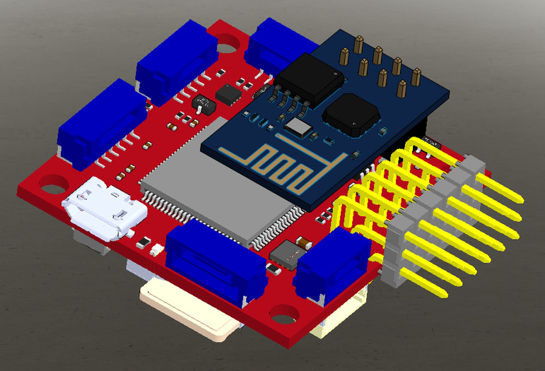
Pixracer
The Pixhawk® XRacer board family is optimized for small racing quads and planes. In contrast to Pixfalcon and Pixhawk it has in-built Wifi, new sensors, convenient full servo headers, CAN and supports 2M flash.

主要特性
- Main System-on-Chip: STM32F427VIT6 rev.3
- CPU: 180 MHz ARM Cortex® M4 with single-precision FPU
- RAM: 256 KB SRAM (L1)
- Standard FPV form factor: 36x36 mm with standard 30.5 mm hole pattern
- Invensense® ICM-20608 Accel / Gyro (4 KHz) / MPU9250 Accel / Gyro / Mag (4 KHz)
- HMC5983 magnetometer with temperature compensation
- Measurement Specialties MS5611 barometer
- JST GH connectors
- microSD (logging)
- Futaba S.BUS and S.BUS2 / Spektrum DSM2 and DSMX / Graupner SUMD / PPM input / Yuneec ST24
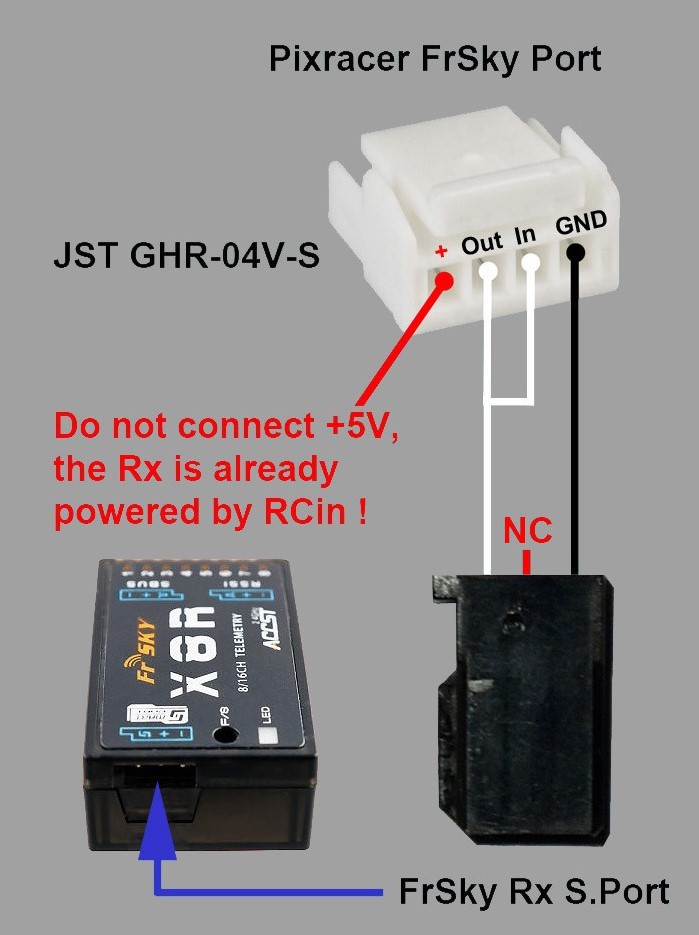
- FrSky® telemetry port
- OneShot PWM out (configurable)
- Optional: Safety switch and buzzer
Where to Buy
Pixracer is available from the mRobotics.io.
Accessories include:
- Digital airspeed sensor
- HKPilot Transceiver Telemetry Radio Set V2 (915Mhz - US Telemetry)
- Hobbyking® OSD + EU Telemetry (433 MHz)
Kit
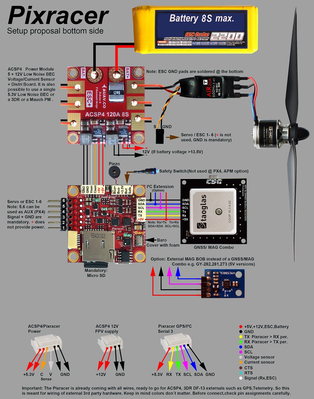
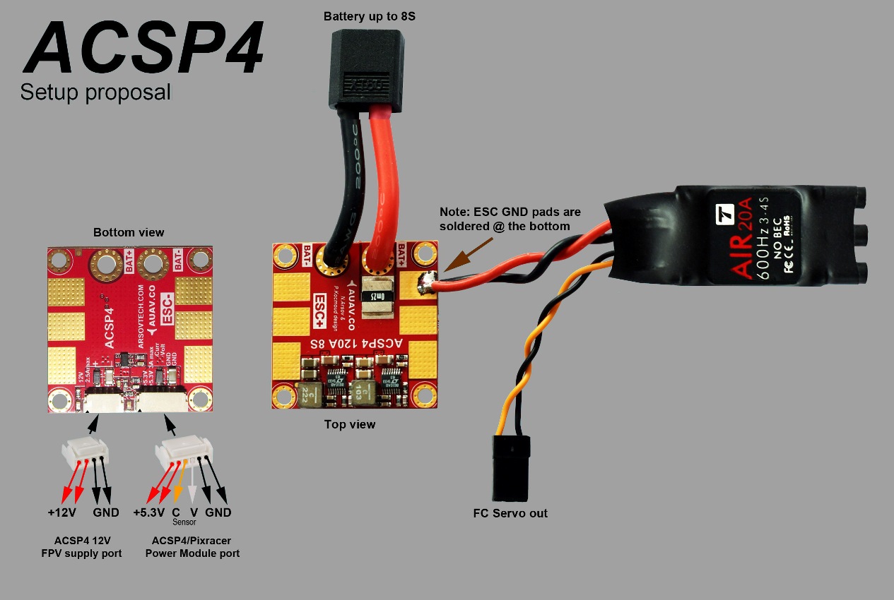
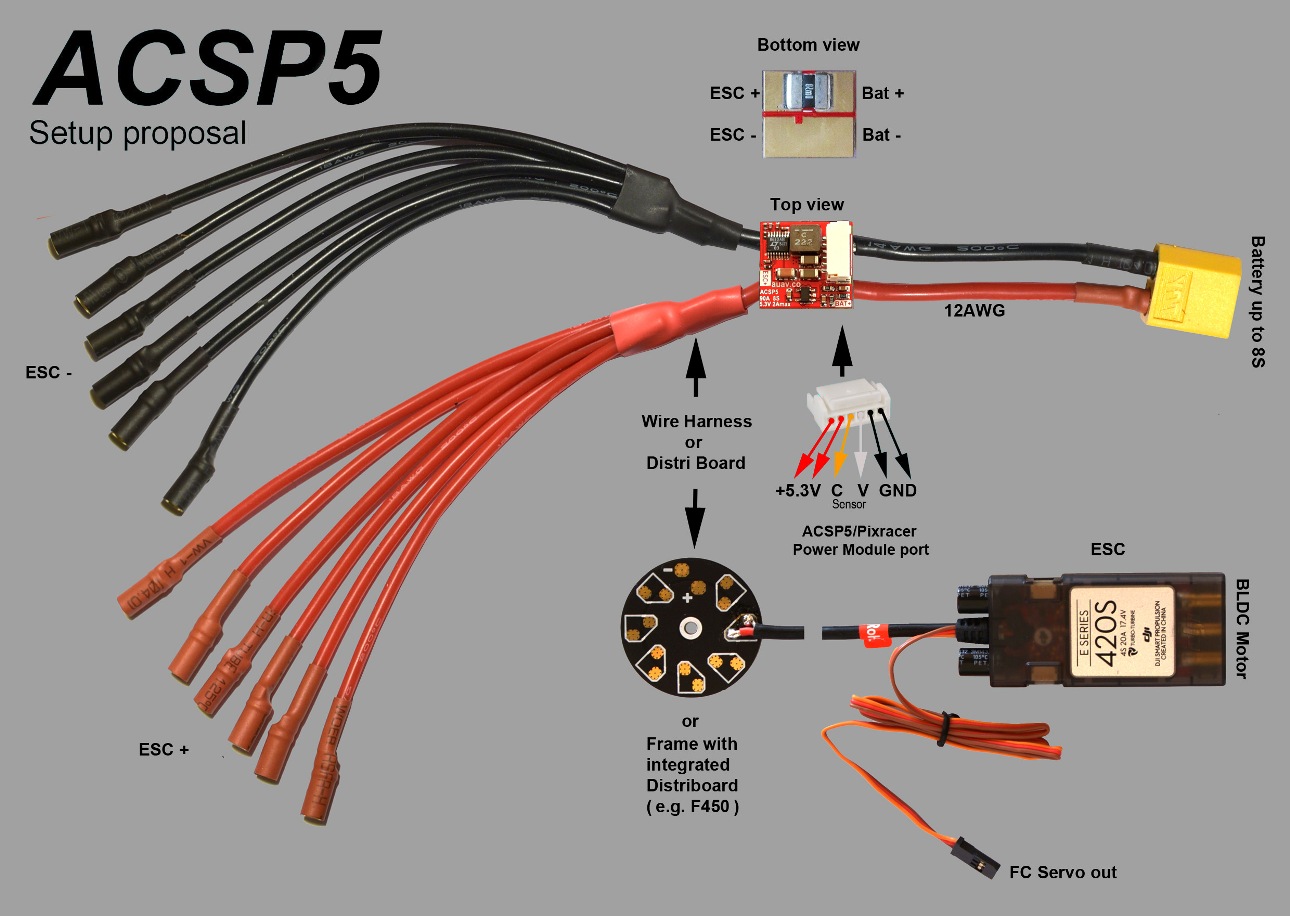
The Pixracer is designed to use a separate avionics power supply. This is necessary to avoid current surges from motors or ESCs to flow back to the flight controller and disturb its delicate sensors.
- Power module (with voltage and current sensing)
- I2C splitter (supporting AUAV, Hobbyking and 3DR® peripherals)
- Cable kit for all common peripherals
Wifi (no USB required)
One of the main features of the board is its ability to use Wifi for flashing new firmware, system setup and in-flight telemetry. This frees it of the need of any desktop system.
Todo Setup and telemetry are already available, firmware upgrade is already supported by the default bootloader but not yet enabled
- ESP8266 Wifi
- Custom ESP8266 MAVLink firmware
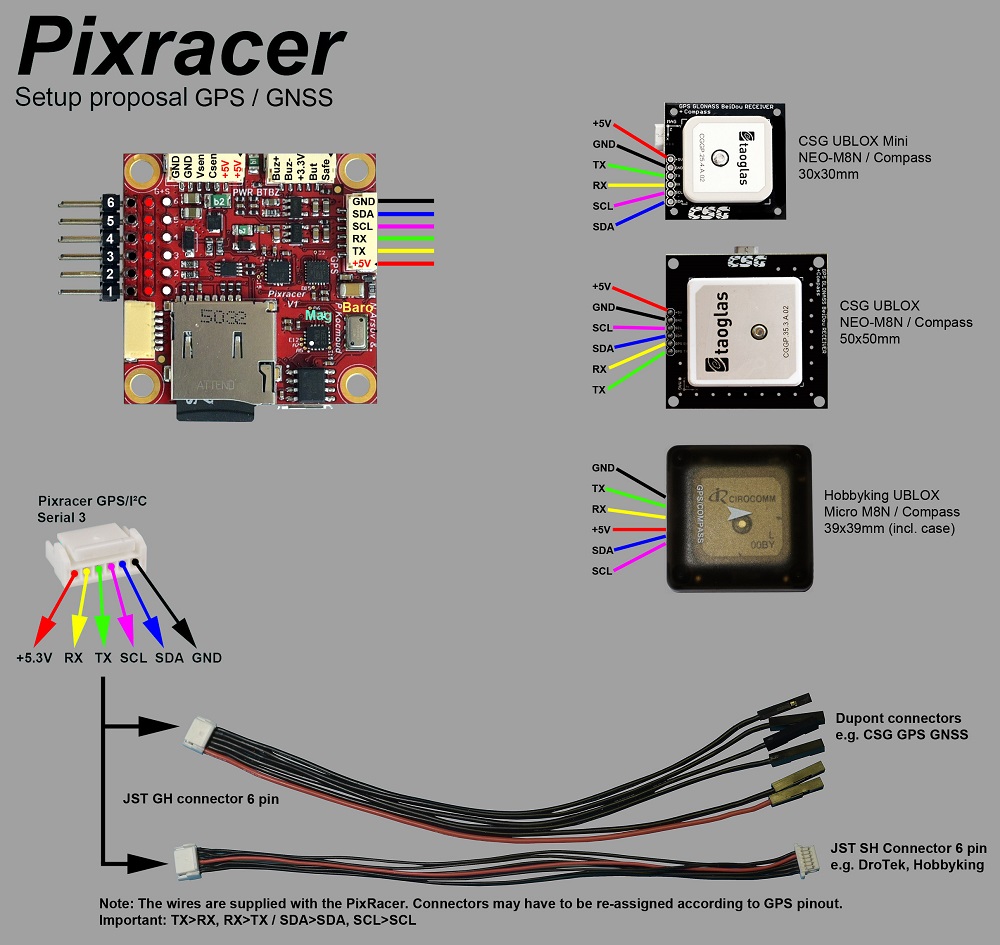
Wiring Diagrams
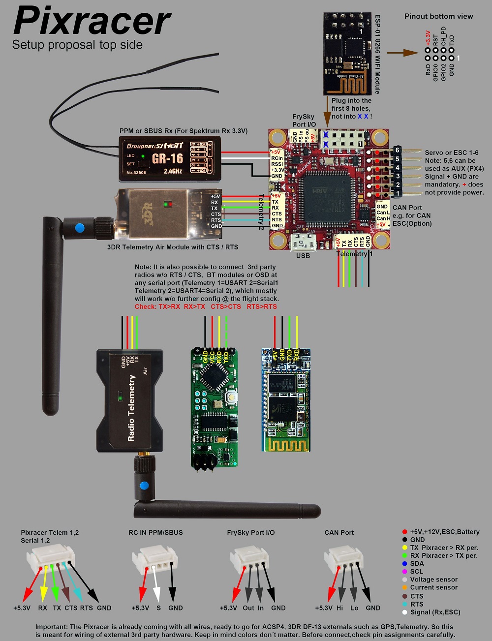
连接器
All connectors follow the Dronecode connector standard. Unless noted otherwise all connectors are JST GH.
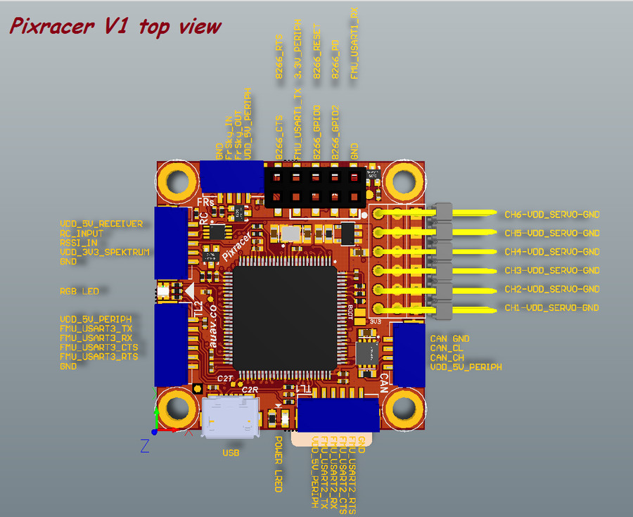
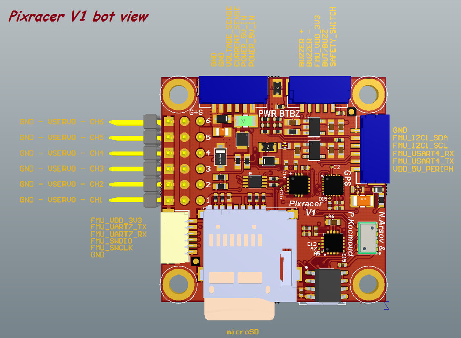
针脚定义
TELEM1, TELEM2+OSD ports
| 针脚 | 信号 | 电压 |
|---|---|---|
| 1 (red) | VCC | +5V |
| 2 (blk) | TX (OUT) | +3.3V |
| 3 (blk) | RX (IN) | +3.3V |
| 4 (blk) | CTS (IN) | +3.3V |
| 5 (blk) | RTS (OUT) | +3.3V |
| 6 (blk) | GND | GND |
GPS port
| 针脚 | 信号 | 电压 |
|---|---|---|
| 1 (red) | VCC | +5V |
| 2 (blk) | TX (OUT) | +3.3V |
| 3 (blk) | RX (IN) | +3.3V |
| 4 (blk) | I2C1 SCL | +3.3V |
| 5 (blk) | I2C1 SDA | +3.3V |
| 6 (blk) | GND | GND |
FrSky Telemetry / SERIAL4
| 针脚 | 信号 | 电压 |
|---|---|---|
| 1 (red) | VCC | +5V |
| 2 (blk) | TX (OUT) | +3.3V |
| 3 (blk) | RX (IN) | +3.3V |
| 4 (blk) | GND | GND |
RC Input (accepts PPM / S.BUS / Spektrum / SUMD / ST24)
| 针脚 | 信号 | 电压 |
|---|---|---|
| 1 (red) | VCC | +5V |
| 2 (blk) | RC IN | +3.3V |
| 3 (blk) | RSSI IN | +3.3V |
| 4 (blk) | VDD 3V3 | +3.3V |
| 5 (blk) | GND | GND |
CAN
| 针脚 | 信号 | 电压 |
|---|---|---|
| 1 (red) | VCC | +5V |
| 2 (blk) | CAN_H | +12V |
| 3 (blk) | CAN_L | +12V |
| 4 (blk) | GND | GND |
POWER
| 针脚 | 信号 | 电压 |
|---|---|---|
| 1 (red) | VCC | +5V |
| 2 (blk) | VCC | +5V |
| 3 (blk) | CURRENT | +3.3V |
| 4 (blk) | VOLTAGE | +3.3V |
| 5 (blk) | GND | GND |
| 6 (blk) | GND | GND |
SWITCH
| 针脚 | 信号 | 电压 |
|---|---|---|
| 1 (red) | SAFETY | GND |
| 2 (blk) | !IO_LED_SAFETY | GND |
| 3 (blk) | VCC | +3.3V |
| 4 (blk) | BUZZER- | - |
| 5 (blk) | BUZZER+ | - |
Dronecode debug port (JST SM06B connector)
| 针脚 | 信号 | 电压 |
|---|---|---|
| 1 (red) | VCC TARGET SHIFT | +3.3V |
| 2 (blk) | CONSOLE TX (OUT) | +3.3V |
| 3 (blk) | CONSOLE RX (IN) | +3.3V |
| 4 (blk) | SWDIO | +3.3V |
| 5 (blk) | SWCLK | +3.3V |
| 6 (blk) | GND | GND |
Schematics
The reference is provided as: Altium Design Files
The following PDF files are provided for convenience only:
- pixracer-rc12-12-06-2015-1330.pdf
- pixracer-r14.pdf - R14 or RC14 is printed next to the SDCard socket
编译固件
Tip大多数用户将不需要建立此固件! 它是预构建的, 并在连接适当的硬件时由 QGroundControl 自动安装。
为此目标 编译 PX4:
make px4_fmu-v4_default
鸣谢
This design was created by Nick Arsov and Phillip Kocmoud and architected by Lorenz Meier, David Sidrane and Leonard Hall.
