 我的书签
我的书签
 添加书签
添加书签 移除书签
移除书签- DJI FlameWheel 450 + CUAV V5 nano Build
- Bill of materials
- Hardware
- Frame
- CUAV v5 nano Package
- Electronics
- Tools needed
- Assembly
- Vehicle Configuration/Calibration {#configure}
- Tuning
- Video
- Acknowledgments
DJI FlameWheel 450 + CUAV V5 nano Build
This topic provides full instructions for building the kit and configuring PX4 using QGroundControl.
Key information
- Frame: DJI F450
- Flight controller: CUAV V5 nano
- Assembly time (approx.): 90 minutes (45 minutes for frame, 45 minutes autopilot installation/configuration)
Bill of materials
The components needed for this build are:
- Flight controller: CUAV V5 nano:
- GPS: CUAV NEO V2 GPS
- Power Module
- Frame: DJI F450
- Propellers: DJI Phantom Built-in Nut Upgrade Propellers 9.4x5
- Battery: Turnigy High Capacity 5200mAh 3S 12C Lipo Pack w/XT60
- Telemetry: Holibro Transceiver Telemetry Radio V3
- RC Receiver: FrSky D4R-II 2.4G 4CH ACCST Telemetry Receiver
- Motors: DJI E305 2312E Motor (800kv,CW)
- ESC: Hobbywing XRotor 20A APAC Brushless ESC 3-4S For RC Multicopters
In addition, we used an FrSky Taranis controller. You will also need zip ties, double-sided tape, a soldering iron.
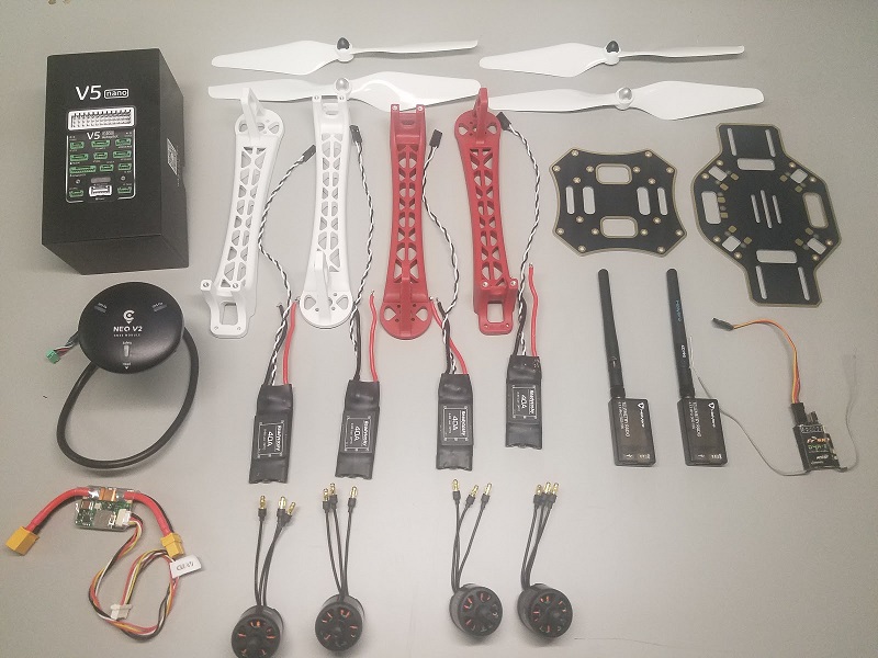
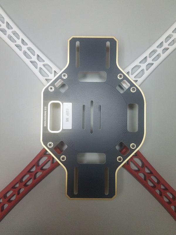
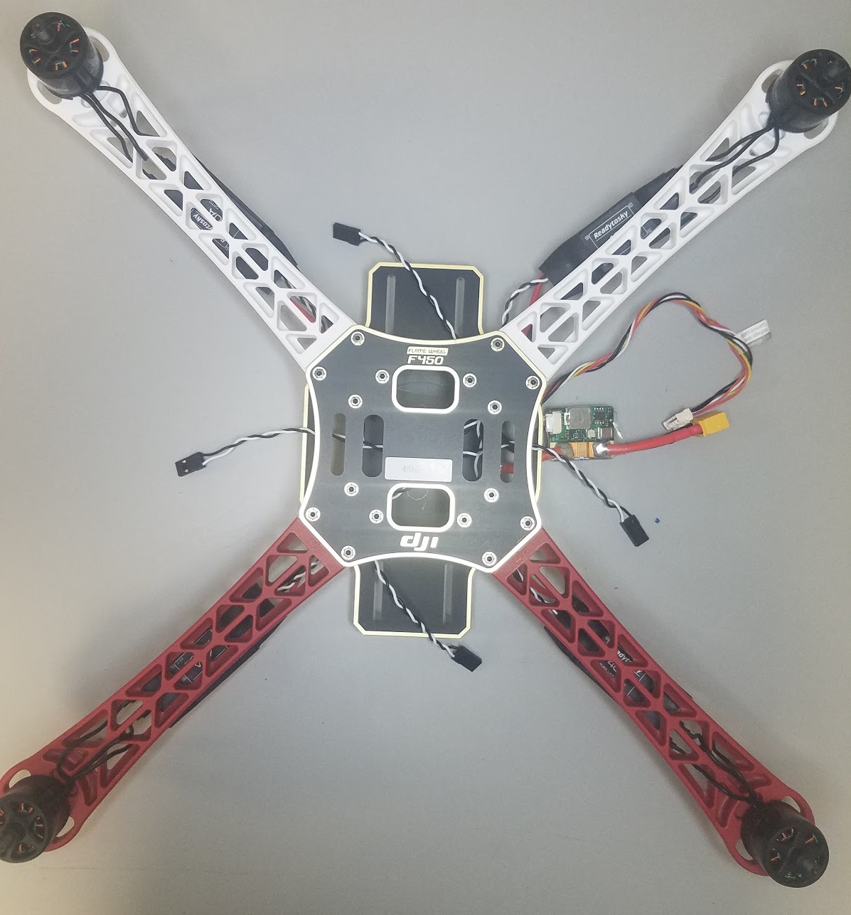
The image below shows both frame and electronic components.
Hardware
Frame
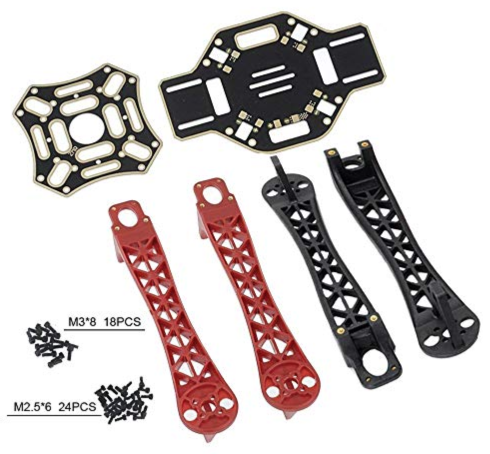
This section lists all hardware for the frame.
| Description | Quantity |
|---|---|
| DJI F450 Bottom plate | 1 |
| DJI F450 Top plate | 1 |
| DJI F450 legs with landing gear | 4 |
| M3*8 screws | 18 |
| M2 5*6 screws | 24 |
| Velcro Battery Strap | 1 |
| DJI Phantom Built-in Nut Upgrade Propellers 9.4x5 | 1 |
CUAV v5 nano Package
This section lists the components in the CUAV v5 nano package.
| Description | Quantity (Default Package) | Quantity (+GPS Package) |
|---|---|---|
| V5 nano flight controller | 1 | 1 |
| DuPont Cable | 2 | 2 |
| I2C/CAN Cable | 2 | 2 |
| ADC 6.6 Cable | 2 | 2 |
| SBUS Signal Cable | 1 | 1 |
| IRSSI Cable | 1 | 1 |
| DSM Signal Cable | 1 | 1 |
| ADC 3.3 Cable | 1 | 1 |
| Debug Cable | 1 | 1 |
| Safety Switch Cable | 1 | 1 |
| Voltage & Current Cable | 1 | 1 |
| PW-Link Module Cable | 1 | 1 |
| Power Module | 1 | 1 |
| SanDisk 16GB Memory Card | 1 | 1 |
| 12C Expansion Board | 1 | 1 |
| TTL Plate | 1 | 1 |
| NEO GPS | - | 1 |
| GPS Bracket | - | 1 |
Electronics
| Description | Quantity |
|---|---|
| CUAV V5 nano | 1 |
| CUAV NEO V2 GPS | 1 |
| Holibro Telemetry | 1 |
| FrSky D4R-II 2.4G 4CH ACCST Telemetry Receiver | 1 |
| DJI E305 2312E Motor (800kv,CW) | 4 |
| Hobbywing XRotor 20A APAC Brushless ESC | 4 |
| Power Module(Included in the CUAV V5 nano package) | 1 |
| Turnigy High Capacity 5200mAh 3S 12C Lipo Pack w/XT60 | 1 |
Tools needed
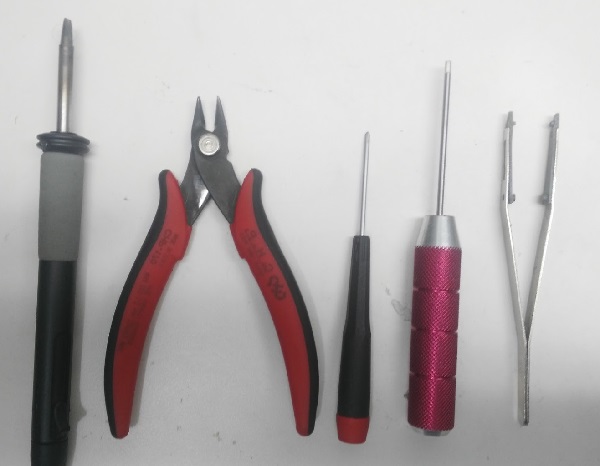
The following tools are used in this assembly:
- 2.0mm Hex screwdriver
- 3mm Phillips screwdriver
- Wire cutters
- Precision tweezers
- Soldering iron
Assembly
Estimated time to assemble is approximately 90 minutes (about 45 minutes for the frame and 45 minutes installing the autopilot and configuring the airframe.
Attach the 4 arms to the bottom plate using the provided screws.
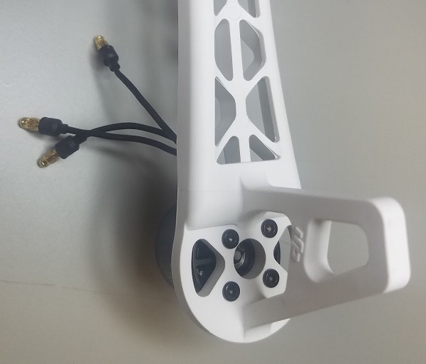
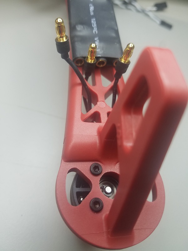
Solder ESC (Electronic Speed Controller) to the board, positive (red) and negative (black).
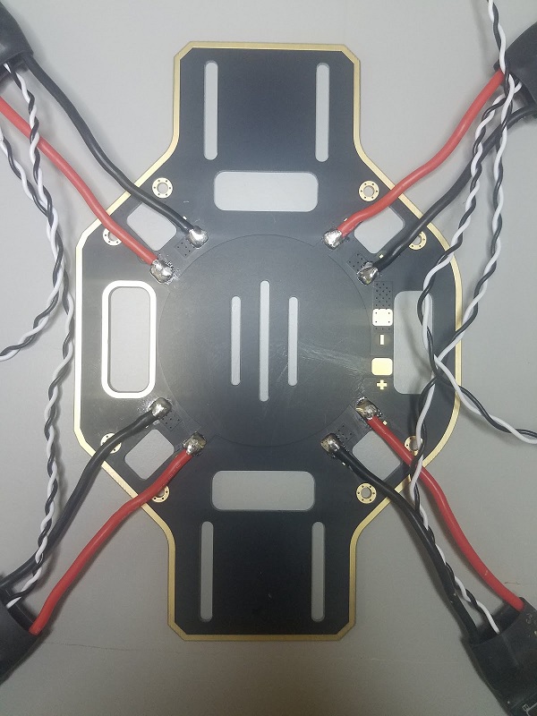
Solder the Power Module, positive (red) and negative (black).
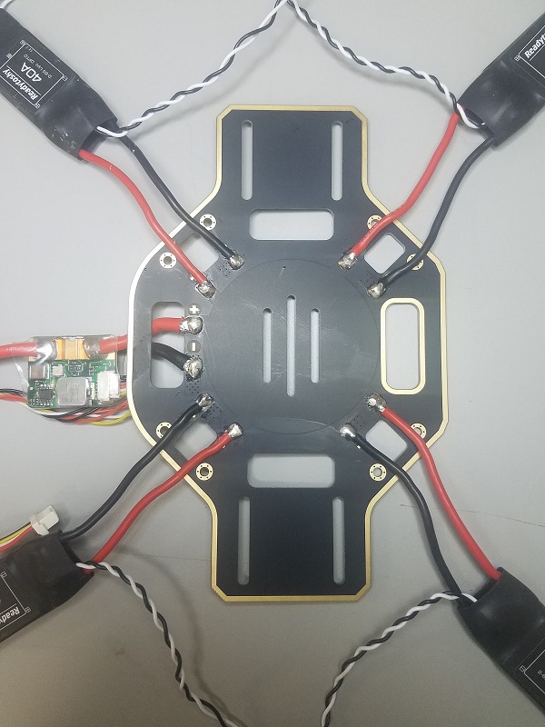
Plug in the motors to the ESCs according to their positions.
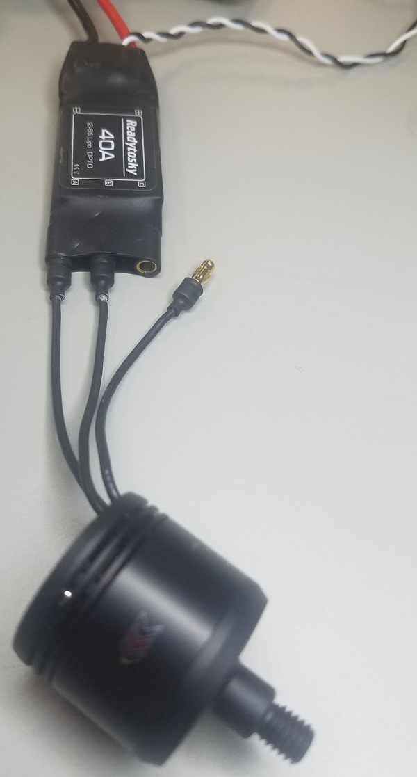
Attach the motors to the corresponding arms.
Add the top board (screw into the top of the legs).
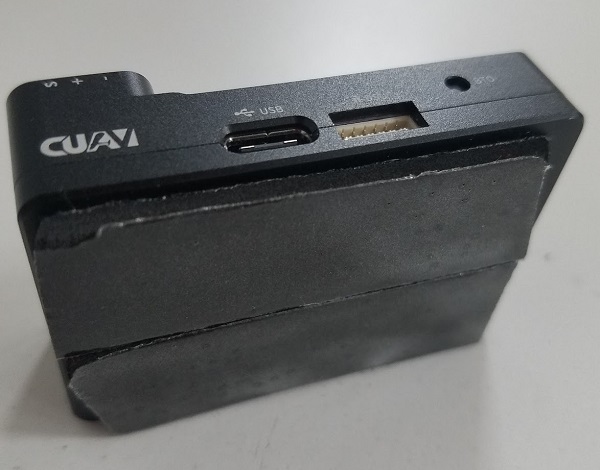
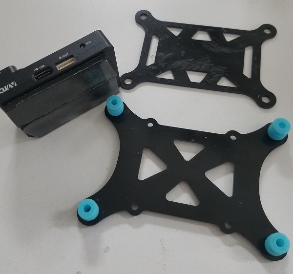
Add damping foam to the CUAV V5 nano flight controller.
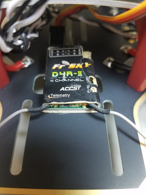
Attach the FrSky receiver to the bottom board with double-sided tape.
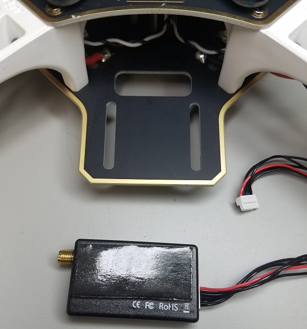
Attach the telemetry module to the vehicle’s bottom board using double-sided tape.
Put the aluminium standoffs on the button plate and attach GPS.
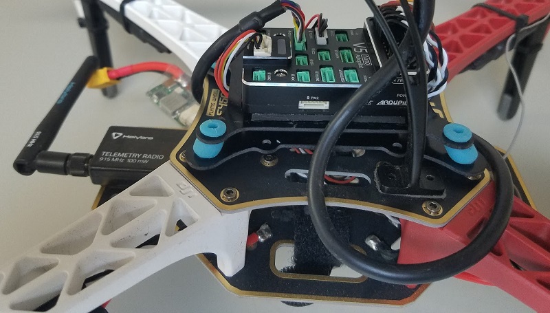
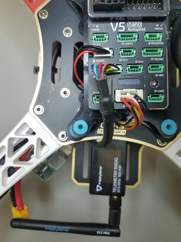
Plug in Telemetry (
TELEM1), GPS module (GPS/SAFETY), RC receiver (RC), all 4 ESC’s (M1-M4), and the power module (Power1) into the flight controller.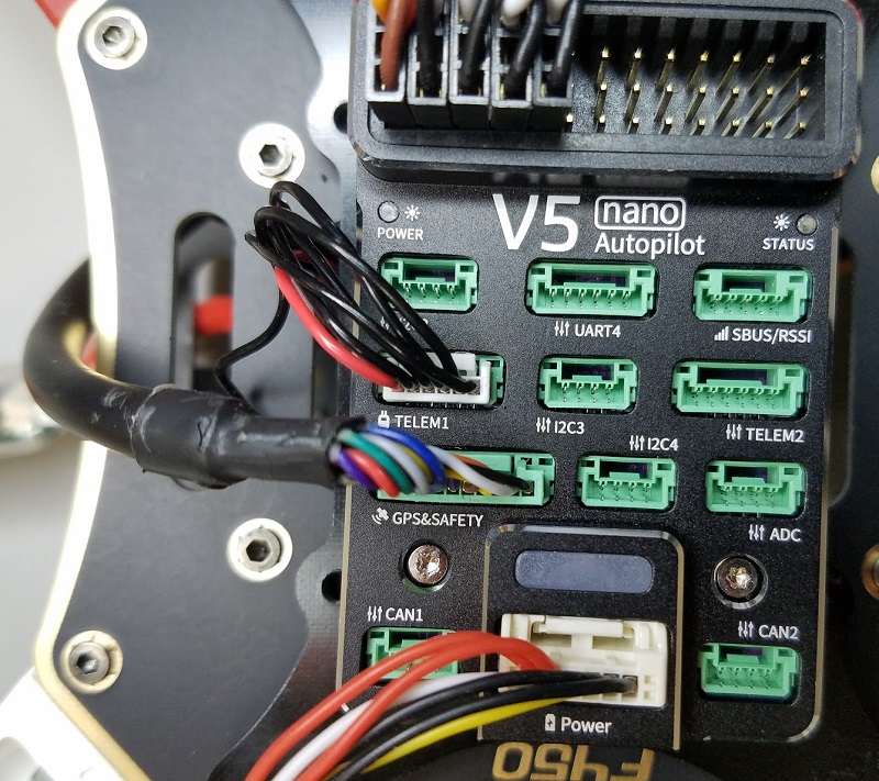
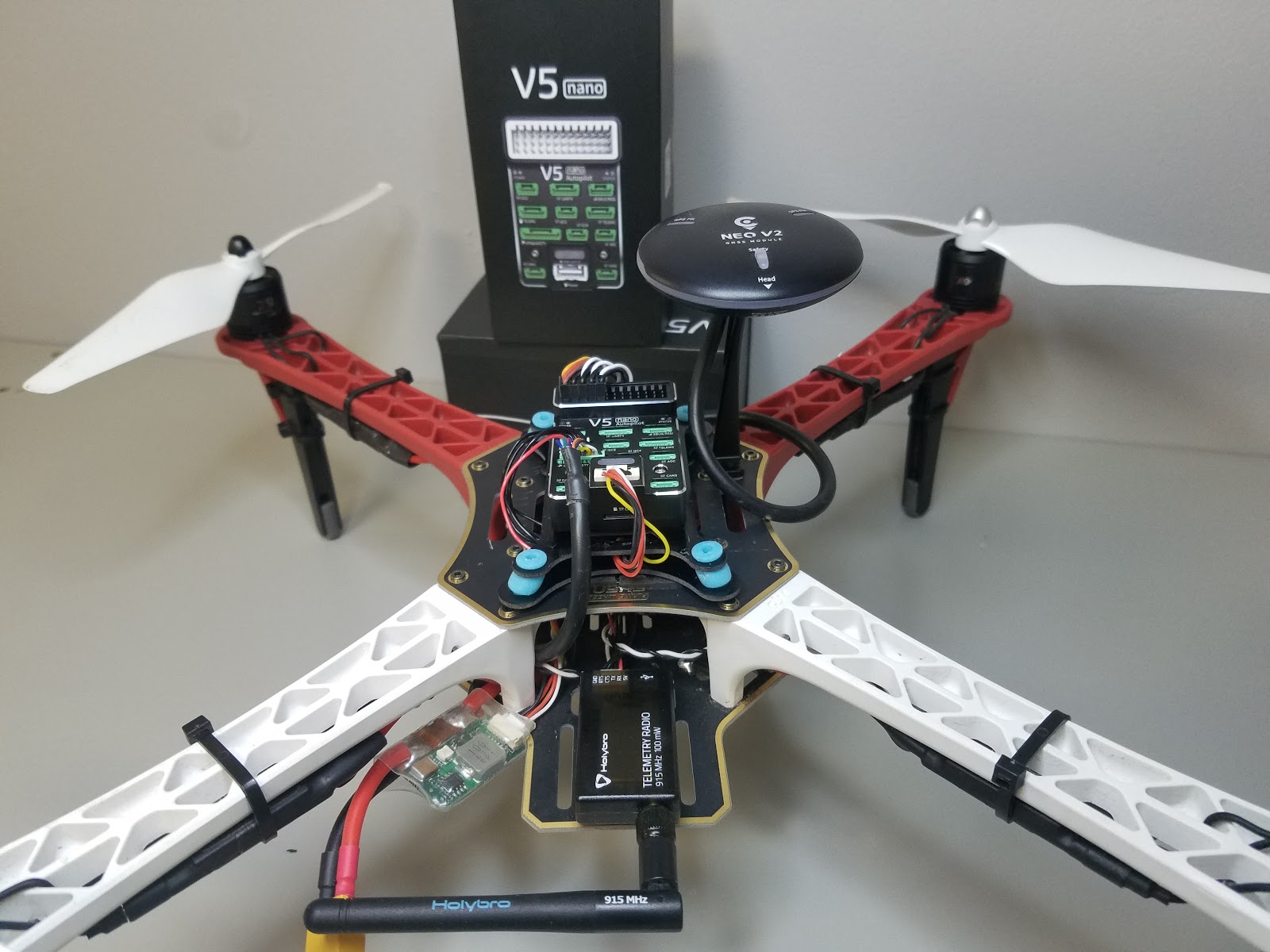
Note The motor order is defined in the Airframe Reference > Quadrotor x
That’s it! The final build is shown below:
Vehicle Configuration/Calibration {#configure}
QGroundControl is used to install the PX4 autopilot and configure/tune it for the frame. Download and install QGroundControl for your platform.
Tip Full instructions for installing and configuring PX4 can be found in Basic Configuration.
First update the firmware and airframe:
- Firmware
Airframe
Note You will need to select the Generic Quadrotor X airframe (Quadrotor x > Generic Quadrotor X).

Then perform the mandatory setup/calibration:
- Sensor Orientation
- Compass
- Accelerometer
- Level Horizon Calibration
- Radio Setup
- Flight Modes > Note For this build we set up modes Stabilized, Altitude and Position on a three-way switch on the receiver (mapped to a single channel - 5). This is the recommended minimal set of modes for beginners.
Ideally you should also do:
- ESC Calibration
- Battery
- Safety
Tuning
Firmware installation sets default autopilot parameters that have been configured for the selected frame. These are good enough to fly with, but it is a good idea to tune the parameters for a specific frame build.
Video
{% youtube %} https://youtu.be/b0bKNdDqVHw {% endyoutube %}
Acknowledgments
This build log was provided by the Dronecode Test Flight Team.
